From Dave's instructions:
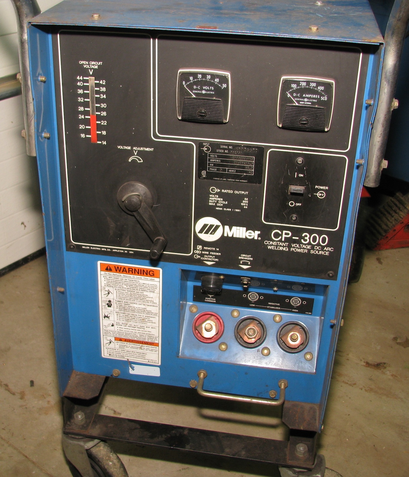
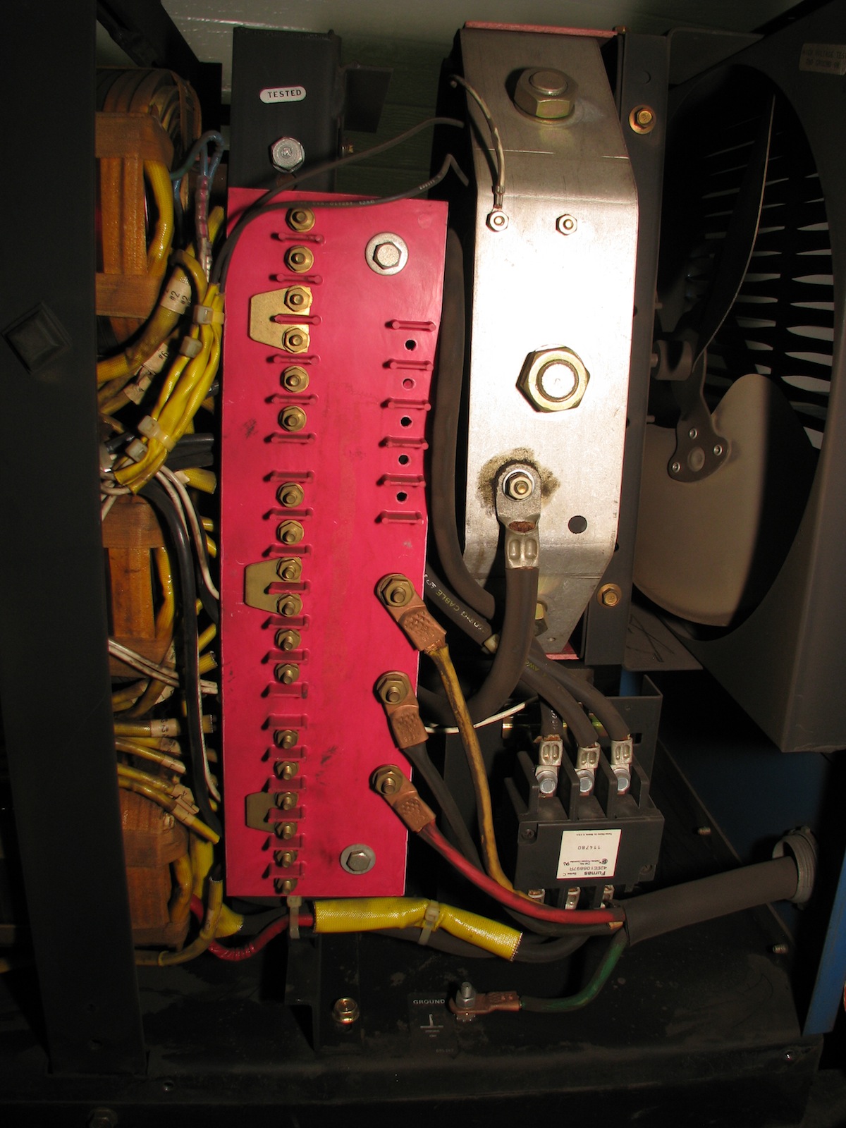
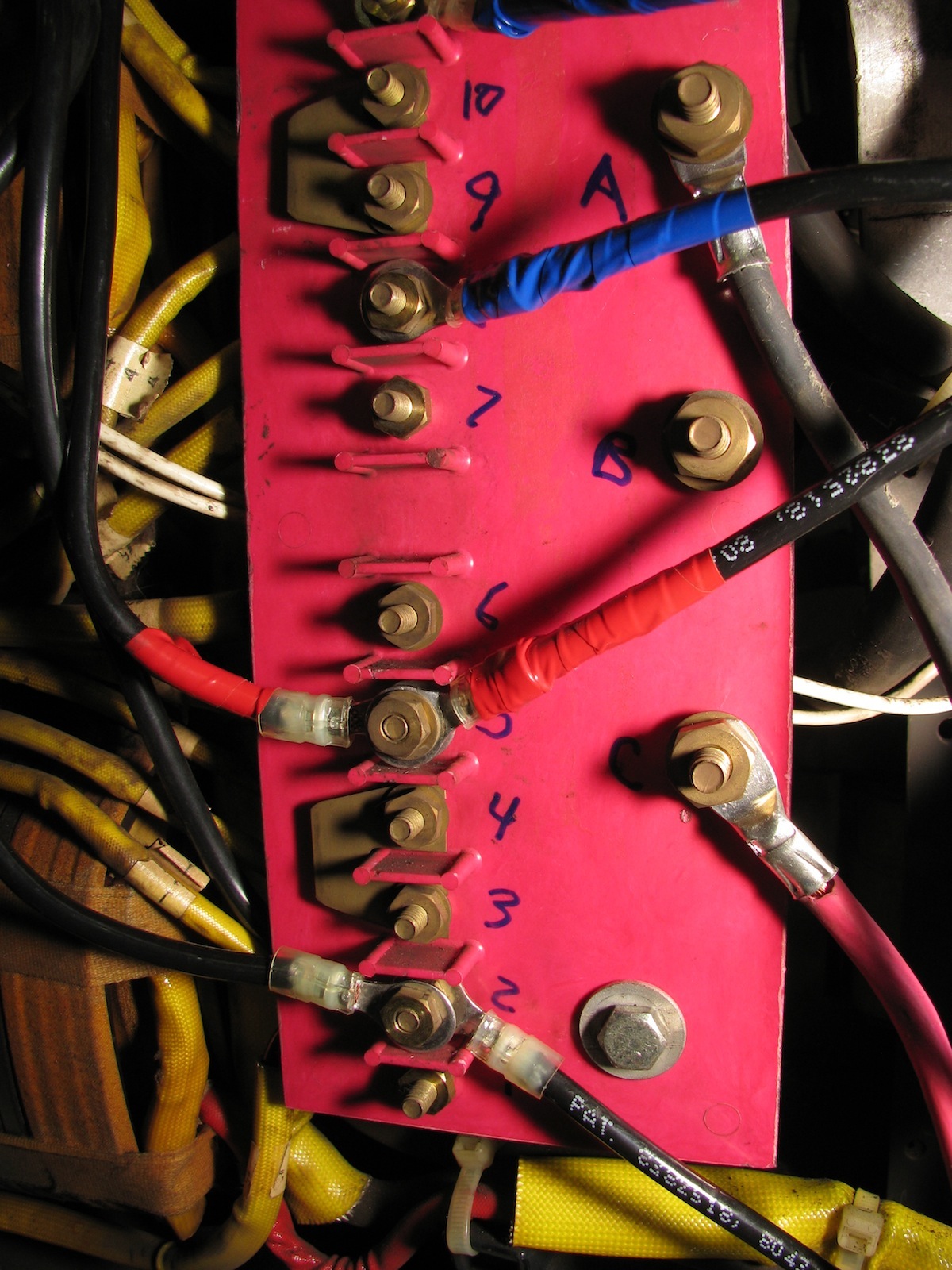
First, find the three main incoming power terminals... that'd be lower right hand side of the main terminal block.
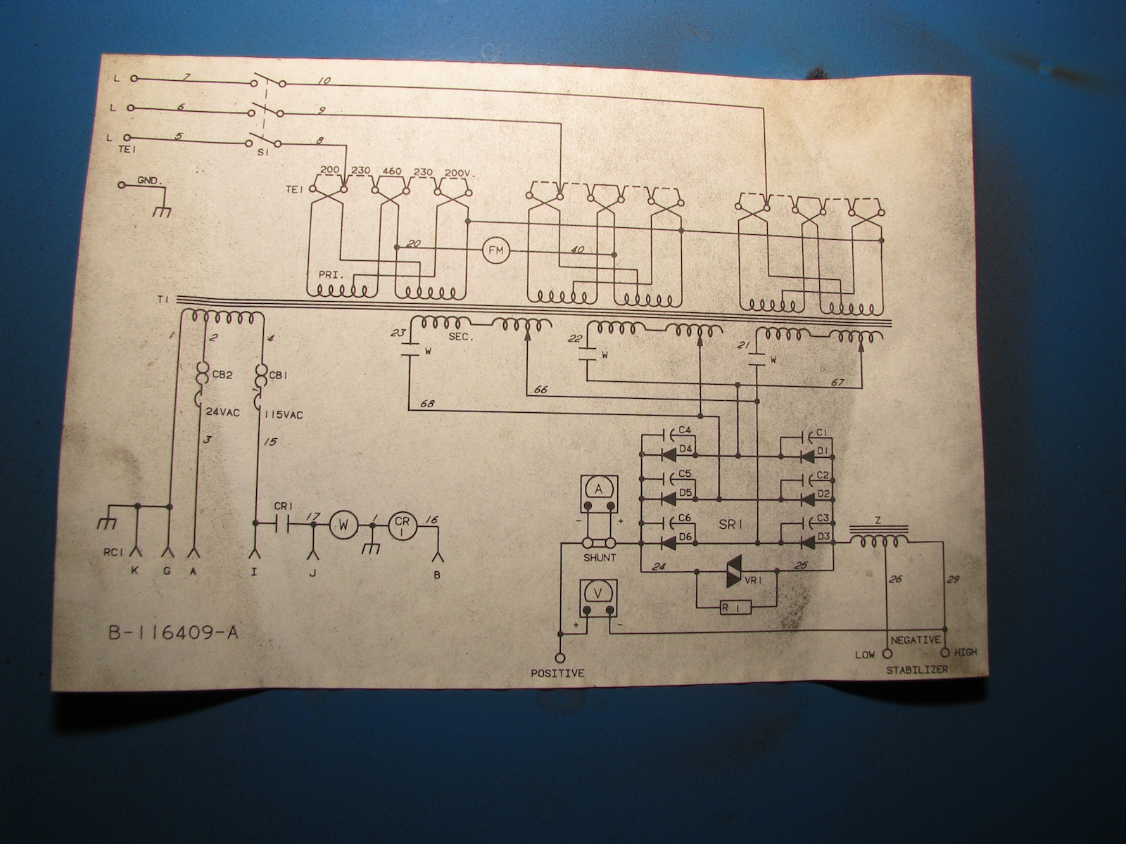
Find wire #5. Label that terminal "C".
Label terminal connected to #6 as "B"
Label terminal connected to #7 as "A".
One difference from Dave's Instructions is that my unit has a dedicated ground.
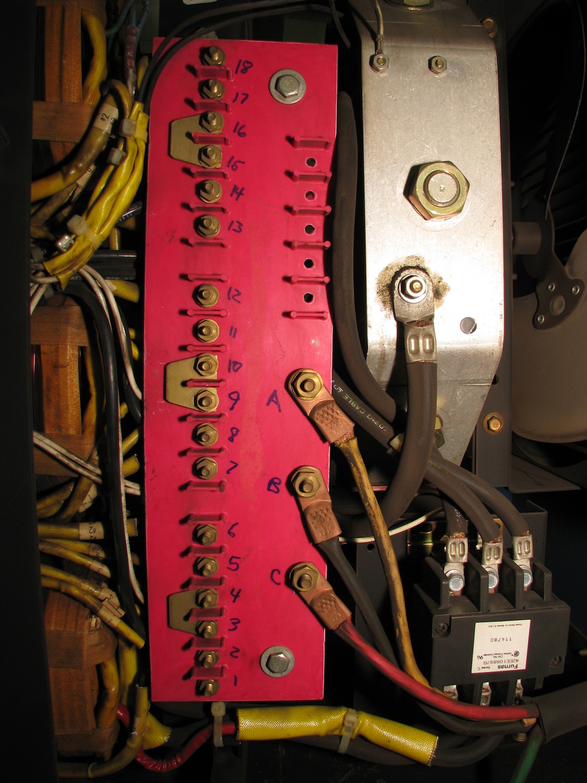
Find Wire #8... it's one of the three at the main power switch. Follow it to the main terminal block. Label it number 2. Label the REST of the terminals on the BIG strip.
On my machine, the numbering started at the bottom:
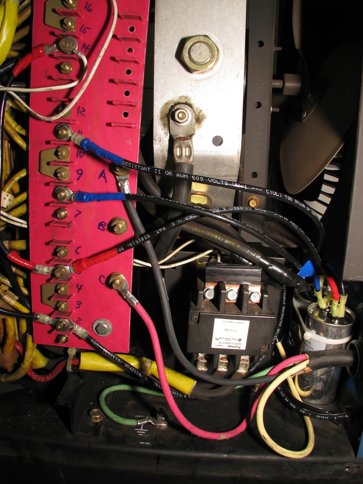
For the next set of steps, I am going to list them in a different way than Dave sent. First, I did all of the work on the back of the terminal strip, then I did the front.
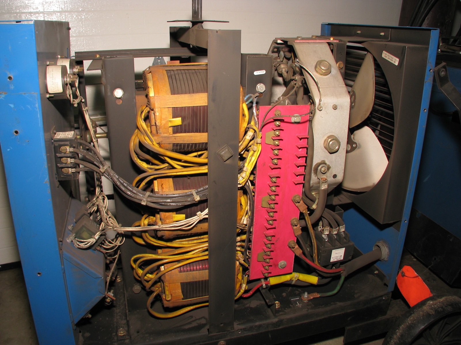
You can see in the picture above that there are two mounting bolts for the terminal strip. Temporarily remove those. Be careful when bending the terminal strip to get to the back. There are lots of solid wires attached to the strip and you do not want to break those wires. I used a very long socket extension to access many of the terminal nuts. Naturally, all of the wires that I needed to remove had additional connectors bolted on top of them. So temporarily remove the outer wire and then remove the desired wire and put the temporarily removed connector back and reinstall the nut. These are brass so do not over tighten.
Back of the Terminal Strip:
Remove Wire 9 from Terminal 8 and tape it (I used friction electrical tape covered by standard electrical tape). Wire 1 had to be temporarily moved in order to remove Wire 9
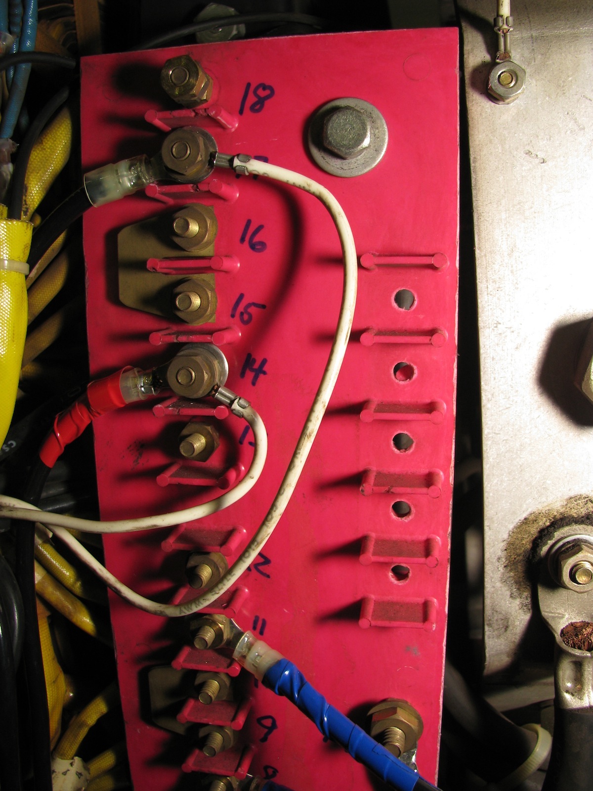
There are two jumper wires attached to terminal 11. One goes to 5 and one goes to 17. Remove the 5 to 11 jumper and remove the 11 to 17 jumper.
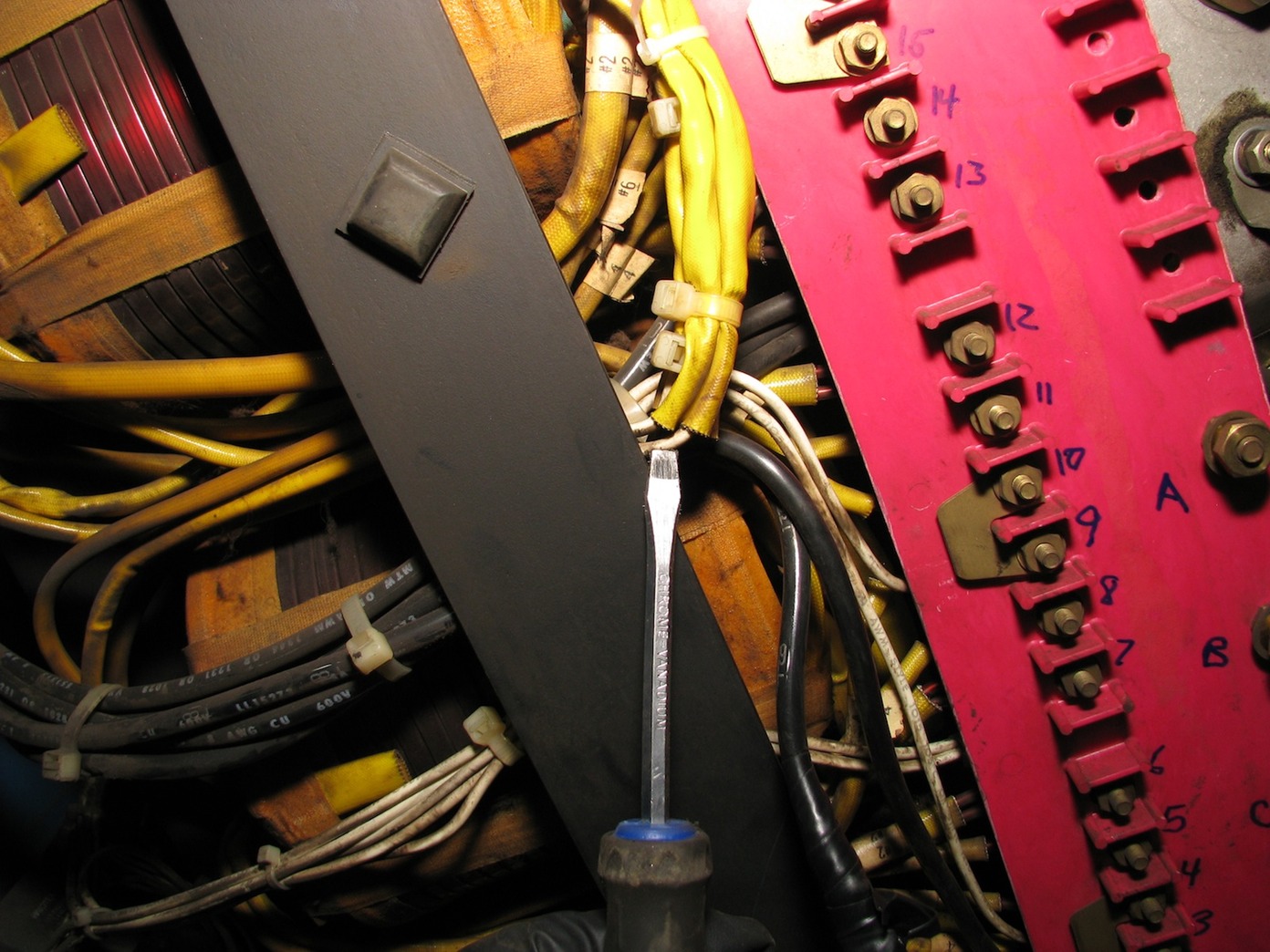
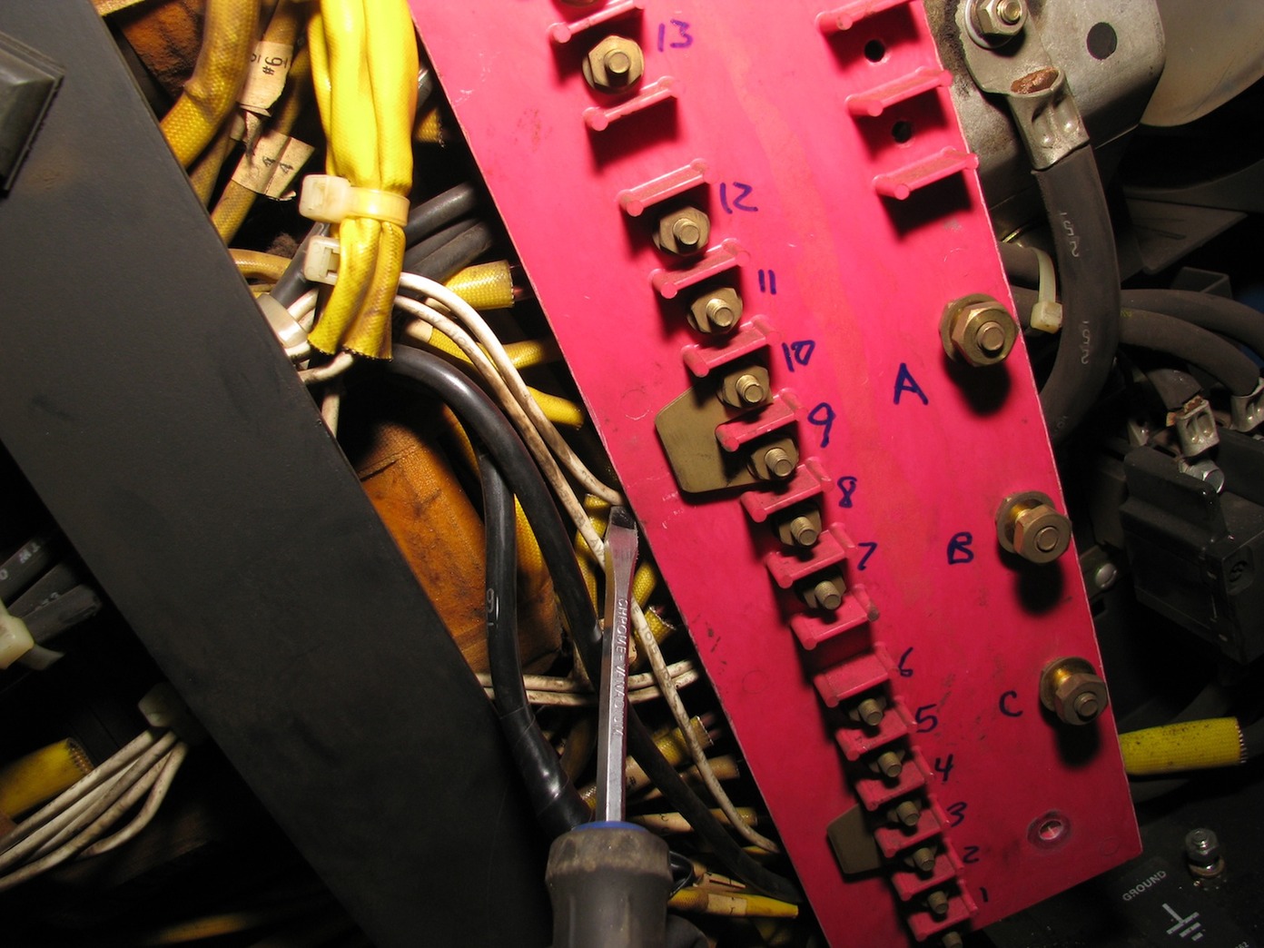
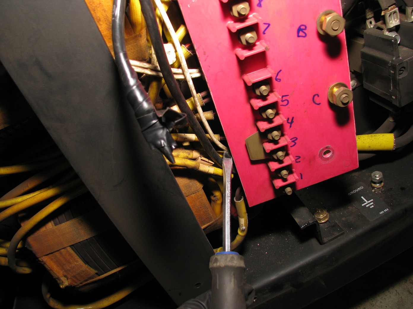
Disconnect the Fan Wires 20 and 40 from the terminal strip. On mine, they were connected to terminals #3 and #9. Push them out of the way for now. They will be remounted at a later time. Here are pictures showing the fan wires on mine (the screwdriver is pointing to them as I trace them):

Reinstall the Terminal Strip mounting bolts. We are now ready to work on the front of the terminal strip.
Front of the Terminal Strip:
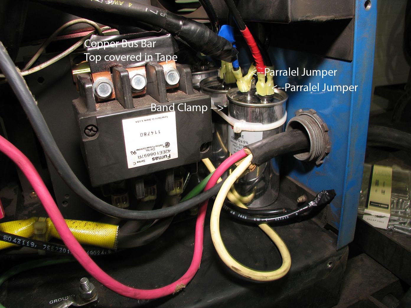
I wanted 130 uf run capacitors but I could not find any at a reasonable price. Instead, I bought a bunch of 65 uF 440V run capacitors - I hooked up 2 of these in parallel for each 130 uf capacitor needed (the rough length of wire required for each capacitor jumper was 5 1/4" before stripping. I did solder bleed resistors (15K Ohm, 5 Watt) between the two pairs of terminals on the capacitor to play it extra safe. I then mounted one of each pair to the back panel with a rubber coated wrap around clamp. The second capacitor was tie wrapped to the first. That can be seen in this picture:
Connect a Blue wire to Terminal #8. The other end goes to one of the capacitors.
Connect two Red Wires to Terminal #5. One goes to Terminal #14. The second goes to one of the capacitors.
Connect a Blue Wire to Terminal #11. The other end is connected to the other capacitor.
Connect two Black Wires to Terminal #2. Connect one to Terminal #17. The second goes to the other set of capacitors.
To summarize the capacitor wiring, one set of capacitors has a Blue wire and a Red wire. THe other set of capacitors has a Blue wire and a Black wire.
The voltage jumpers should be in the 480V locations which are 3-4, 9-10, and 15-16. On my welder, they were already jumpered for 480V.
Connect the two fan wires to the terminal board, one to a Red terminal and the other to a Black terminal. In my case, I used Terminals #14 and #17.
On the secondary side, remove and tape the three large leads connected to the output contactor. As Dave recommended, I made a shorting bar out of 3/4" copper pipe. Install that in place of the 3 leads. Shown in the picture above.
Connect the 240V power cord with Black to Termianl A, Red to Terminal C, and Green to the dedicated ground GND on the floor of the case. Terminal B is left blank. The power cord I used was 3 conductor plus ground so I taped the end of the white wire and left it.
The final wiring is shown in these pictures:
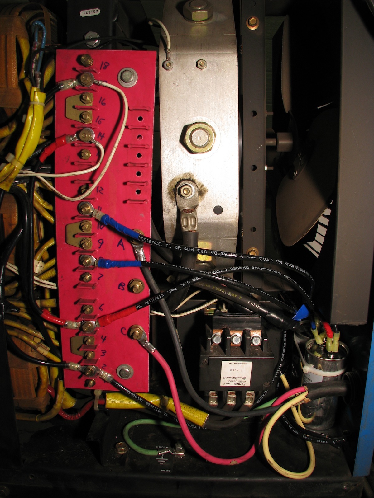
I powered it up and the fan came on with no smoke. Then I unplugged it, put the enclosure back together, connected the wire feeder and tried laying some bead. The welder worked wonderfully. Thank you Dave and Peter!!!!